A Personalized Maze
|
Our project was to make a unique maze, which to me seemed like an easy task at first. However, I would soon learn that it was no simple project.
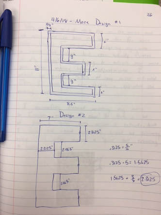
I set out to make a maze of the letter E, the first letter of my name. My first design didn't have any math, so I re-made a design incorporating paths 5/16" wide and the 3'4" border. |
|
|
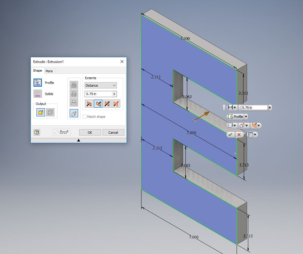
I started my project in Inventor. I drew my E using the line tool and dimensioned it appropriately. Then, I extruded it .75 inches, as outlined in the constraints. Now I can work on the actual path of the maze.
|
|
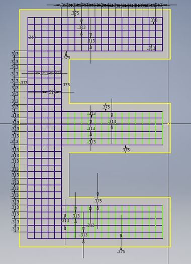
Making a maze is much harder than you might think. You cannot draw the paths and expect it to work. Instead, you have to work with Three-Dimensional walls. I visualized this the best by making a "grid" with squares 5/16" large. Once this was made, I used the trim tool to make my paths.
When trimming the maze down, I had to "skip" every other row because the walls have to be three-dimensional, unlike many mazes on paper. One row/column had to be a path, and the one adjacent was a wall. |
|
|
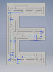
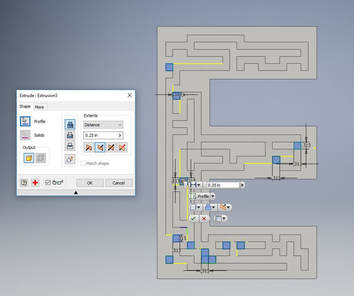
Once I had my maze path drawn, I extruded it 1/4" away from the face of the maze. When I extruded, however, not all of the maze was successfully made. There were several "holes" in my path that shouldn't have been there.
In order to correct this issue, I went back into a new sketch and drew in the squares where the extrusion missed. Then I extruded these squares separately in order to patch my maze. |
|
|
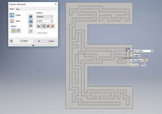
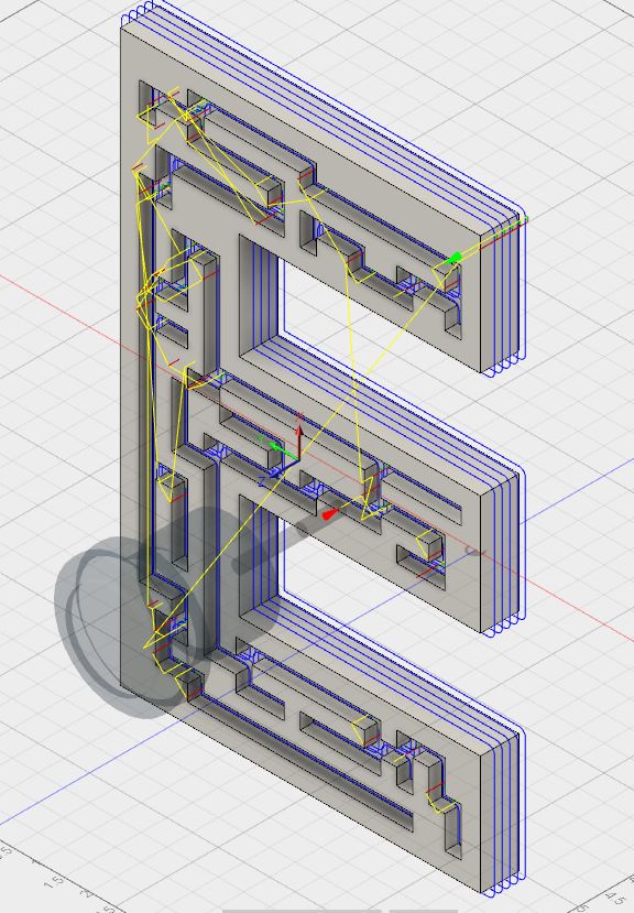
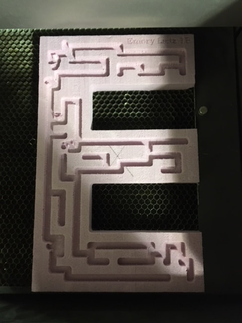
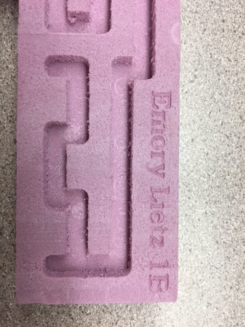
Here's the final product. Try and solve it :)
Now that my maze is modeled in Inventor, I can go to Fusion 360 to convert it into a file compatible with the CNC Router. |
|
Fusion 360
|
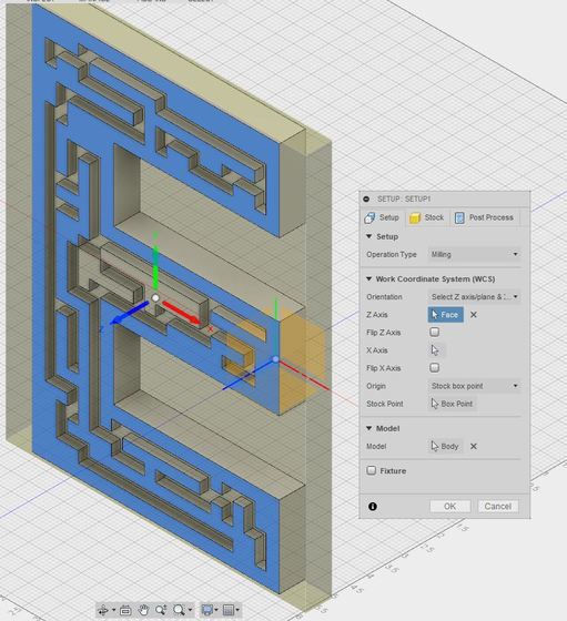
When I uploaded my maze into Fusion 360, the first thing that I had to do was setup the orientation of my maze.
Using the "Setup" tool, I selected the top of my maze surface as the Z Axis, and the bottom edge of the E was the X Axis. Using the "Box Point" tool, I selected the middle of my maze. This is where the CNC router will start drilling my project. |
|
|
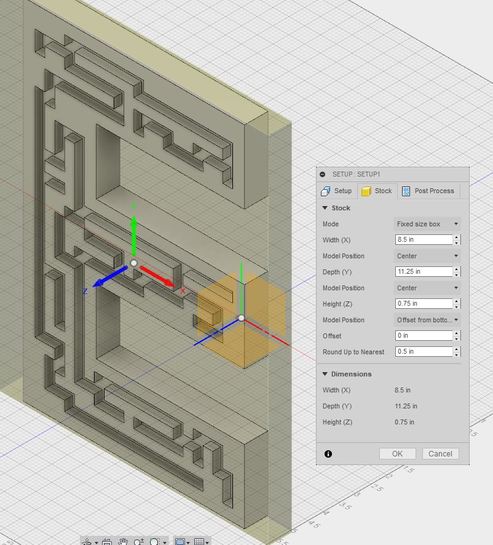
Next, I setup the stock for my project. Stock is the material that you cut your project out of. In this case, we used foam.
My project was 11" tall x 7" long x .75" wide. I dimensioned my stock to be slightly bigger on the top and side, while keeping the width consistent. This way there is room for the drill bit to go around the outside. Finally, in this step I changed the bottom offset to 0 inches. |
|
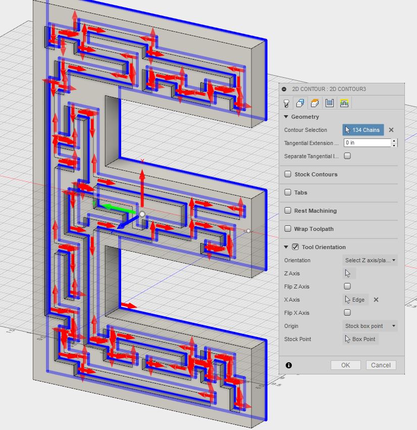
Next, I had to select the route in which the drill would travel. Using the "Contour Selection", I individually selected each line inside of my maze.
It's important to select the bottom of each line in the maze and the bottom edge of the design for this part. The lines should appear blue with a directional arrow coming off of each edge. See left: Here is the toolpath for my maze |
|
|
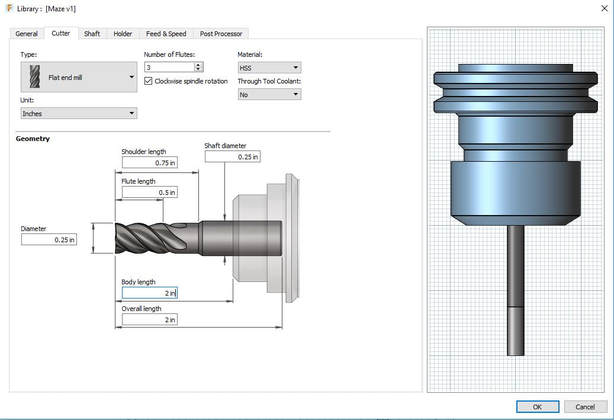
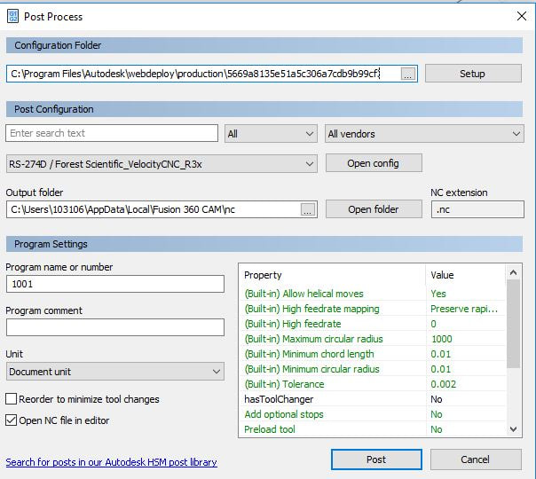
I clicked on the 2D tab at the top of the screen to set up the machine's tool path. First, I selected which tool would be used on the router. For this project, we used a flat end mill with a .25" diameter and a 2" body length.
Once the tool was selected, I changed: Spindle Speed - 10,000 RPM Max Rough Step down - .25" Stock to Leave: 0 |
|
|
Once everything was setup and the simulation looked good, we had to export the file in "GCode", or a code that is compatible with the CNC Router.
I had to make sure the file was under "Forest Scientific" configuration for the router, and I saved the GCode to both my flashdrive and the computer and headed down to the Innovation Center |
|
Router!
|
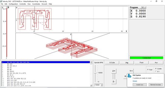
I grabbed a rectangle of foam and marked the middle. I did this by using a straightedge and making an X in the center of the shape.
Then, I "jogged", or moved the drillbit of the router to the middle of the X because that's where I set my box point in Fusion 360. I zeroed the X and Y at this point. Then, I used the "Z Zero Tool" and it automatically set the Z at .600" because that's how long the sensor is. Once everything was set, I hit the run button and was prepared to press the space bar to stop the machine should anything go wrong. |
|

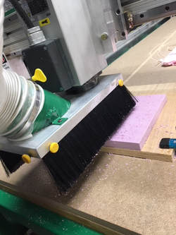
Here are a couple pictures of the router in action. It moves pretty quickly and it spins very fast. The sound it makers when cutting through foam is pretty loud, but Mr. Willauer ran wood later in class, and that was much louder. When it was done, I had to vacuum off the table and surrounding area and I peeled my maze off of the board to admire it.
|

|
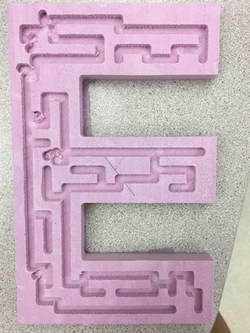
Here's the final product!!!
I'm very happy with how the maze route turned out considering how much I struggled to design it. The white "blobs" that appeared in Fusion 360 actually ended up being part of the routing, but it doesn't actually affect any of the maze's paths.
This maze actually tricked Jon Meinholz with its fake path, so it's successful!!
Laser Engraved?!
|
The last step to making this maze my own was to add my name. I made a file in Illustrator with my name and hour, then I created outlines to just get the outside of the letters. Then, I changed the outlines to blue so that it would just be engraved.
When I got to the laser, I changed the preferences so that blue speed was 100% and power was 14%. I lined up the top edge with the top of the bed and chose my laser space. After checking all corners and turning the exhaust on, I hit play and watched the laser work its magic. |
|
Summary
This was definitely a unit where I learned the most. I learned how to use Fusion 360 to turn an Inventor file into one compatible with both the CNC Router and CNC Mill. I also learned that Fusion 360 is very difficult to use. You have to change many, many settings to convert your file to G-Code and setup the drill bit correctly. The skills I learned in this rotation will certainly come in handy for when I use the CNC Mill to make my brake part. The simulate tool in Fusion is very useful to see how the drill will actually work on your project.
I also learned valuable problem solving skills in this unit. Designing my maze was probably the most challenging experience that I've had this far in IDEA class. I eventually figured it out by using the trim tool and many squares. With the help of Mrs. Proctor, I overcame all the problems I faced and made a very unique maze.
I also learned valuable problem solving skills in this unit. Designing my maze was probably the most challenging experience that I've had this far in IDEA class. I eventually figured it out by using the trim tool and many squares. With the help of Mrs. Proctor, I overcame all the problems I faced and made a very unique maze.
