A Race Car Brake Bracket
|
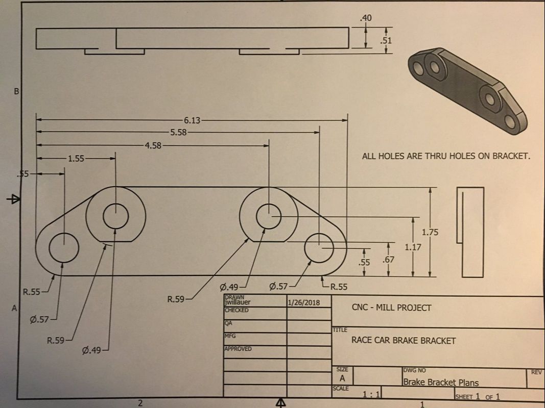
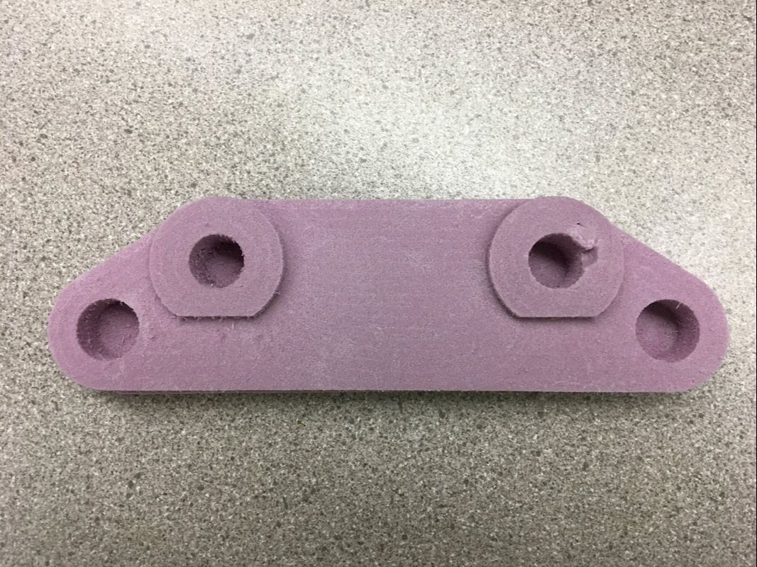
Our task was to fabricate this exact brake bracket (as shown to the right). We will need to use Inventor to model it, Fusion 360 to convert it to G-Code, and the CNC Router to make it out of foam.
|
|
|
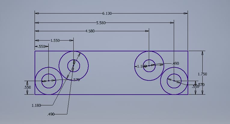
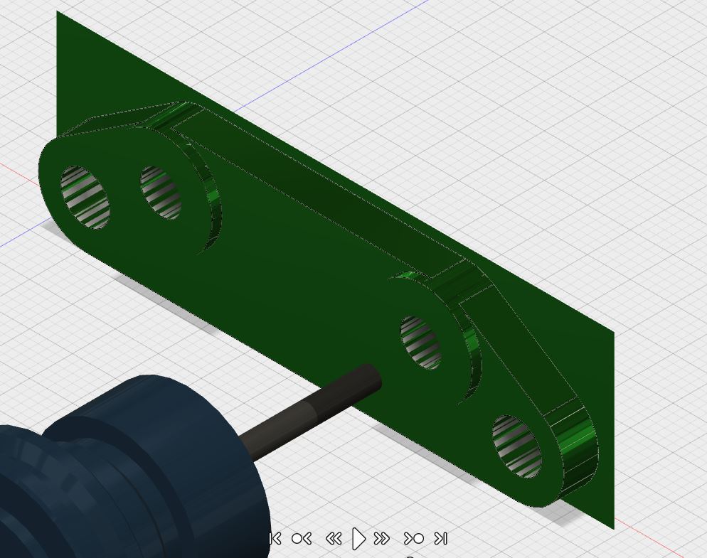
To begin my design, I first made a rectangle with the appropriate height and width dimensions. Then, I added circles and dimensioned them to the correct radii/diameters. I then added circles around the originals to make a "donut" shape.
I used the line tool to connect the circles to the outer edge and then used a new tangent constraint to make sure they lined up with exactly one point on the outer circle. I then used the trim tool to get rid of the extra lines and then I extruded. Finally, I started a brand new sketch and created the raised circles by making two circles and a line that could trim away the bottom of the upper circle. TO top it all off, I extruded that sketch outward and viola. |
|
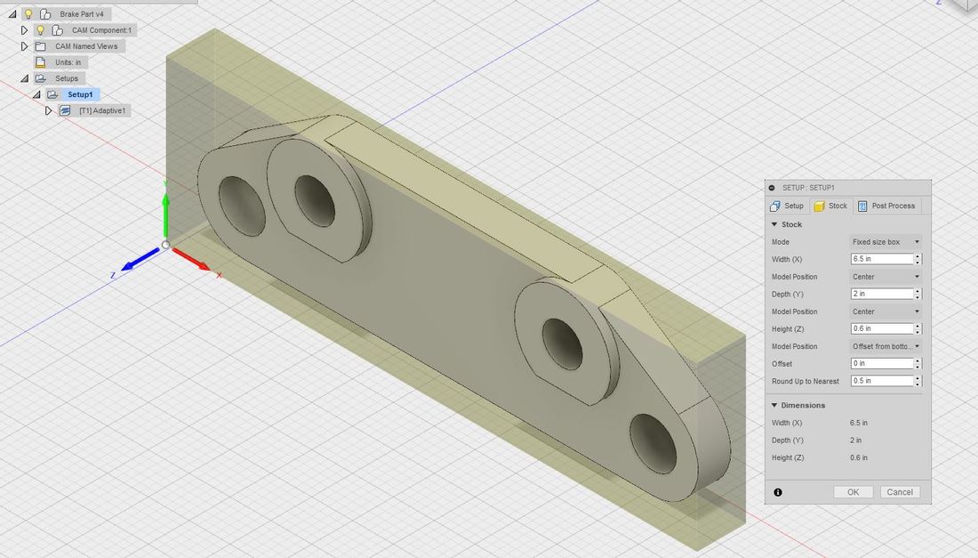
Once I had my brake bracket modeled in Inventor, I loaded it into Fusion 360. After setting the stock and box point to the lower corner, I chose my axes for this project.
|
|
|
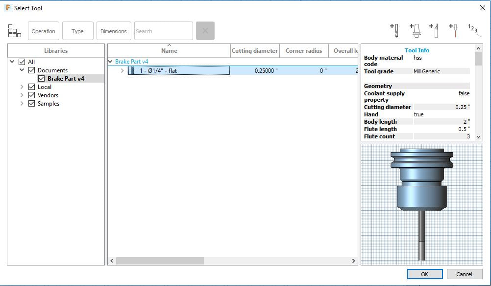
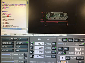
Next, I changed the drill bit and speed of the CNC Mill. For the mill, the spindle speed is 5000 RPM and the Feed Rate is 39.
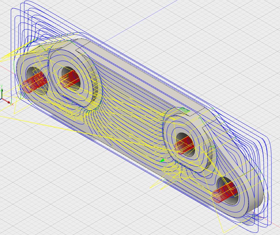
Instead of using the 2D path (like the router), we had to use the 3D - Adaptive Clearing tab for the mill. After changing the max rough stepdown to .25" and the stock to leave to 0, I simulated the bracket and converted it to G-Code. |
|
|
Here's my toolpath from all of my work in Fusion 360.
|
|
CNC Mill!
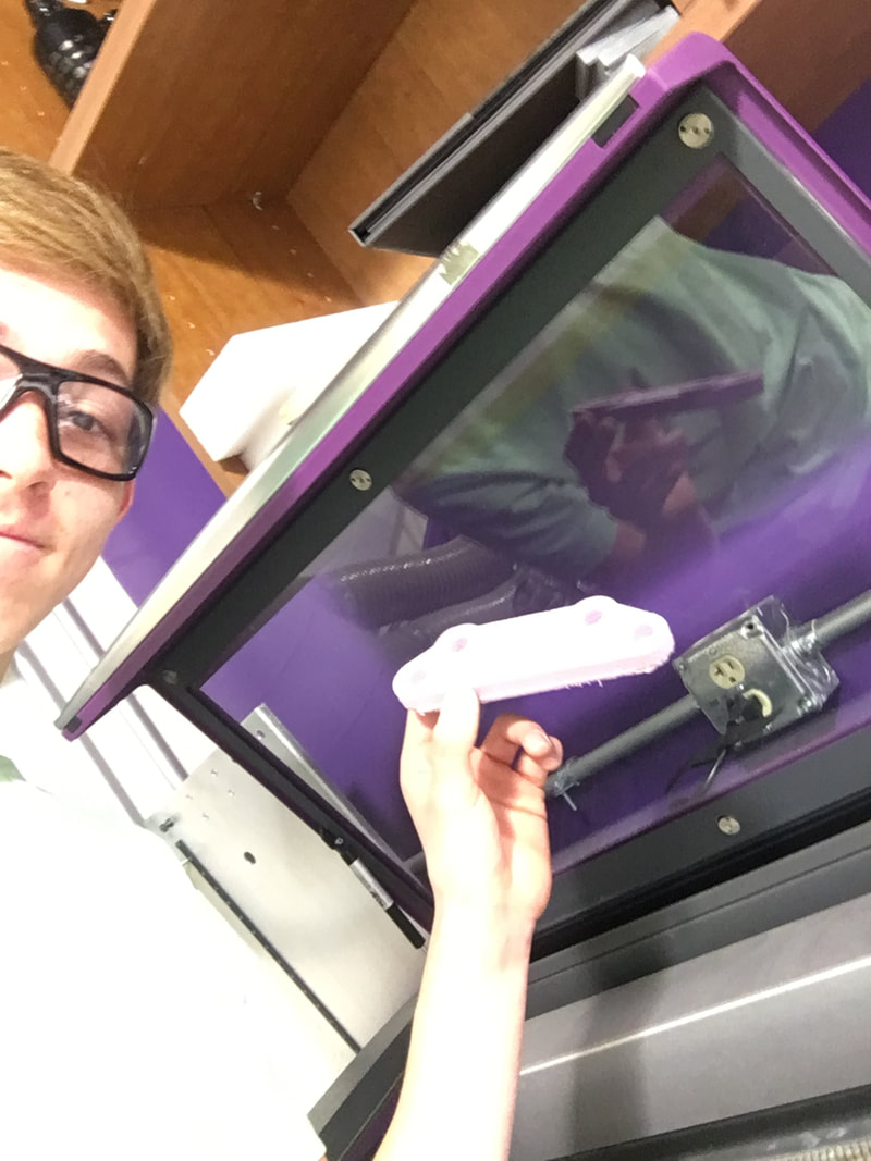
See below: Pictures of me working on the mill.
I found the appropriate sized piece of foam and put double-sided tape on it. I jogged the machine using the neat circular disc. It looked like a video game controller. Finally, my years of experience have come in handy, You could select X, Y, and Z, and the outer circle jogs the machine faster than the inner circle.
I moves the drill bit to the bottom left corner because that's where I set my stock point in Fusion 360. I brought the Z down so that a strip of tape couldn't fit between the drill and the foam. Finally, I closed the doors, pressed play, and waited with a hand on the space bar for something to go wrong.

|
|
|
|
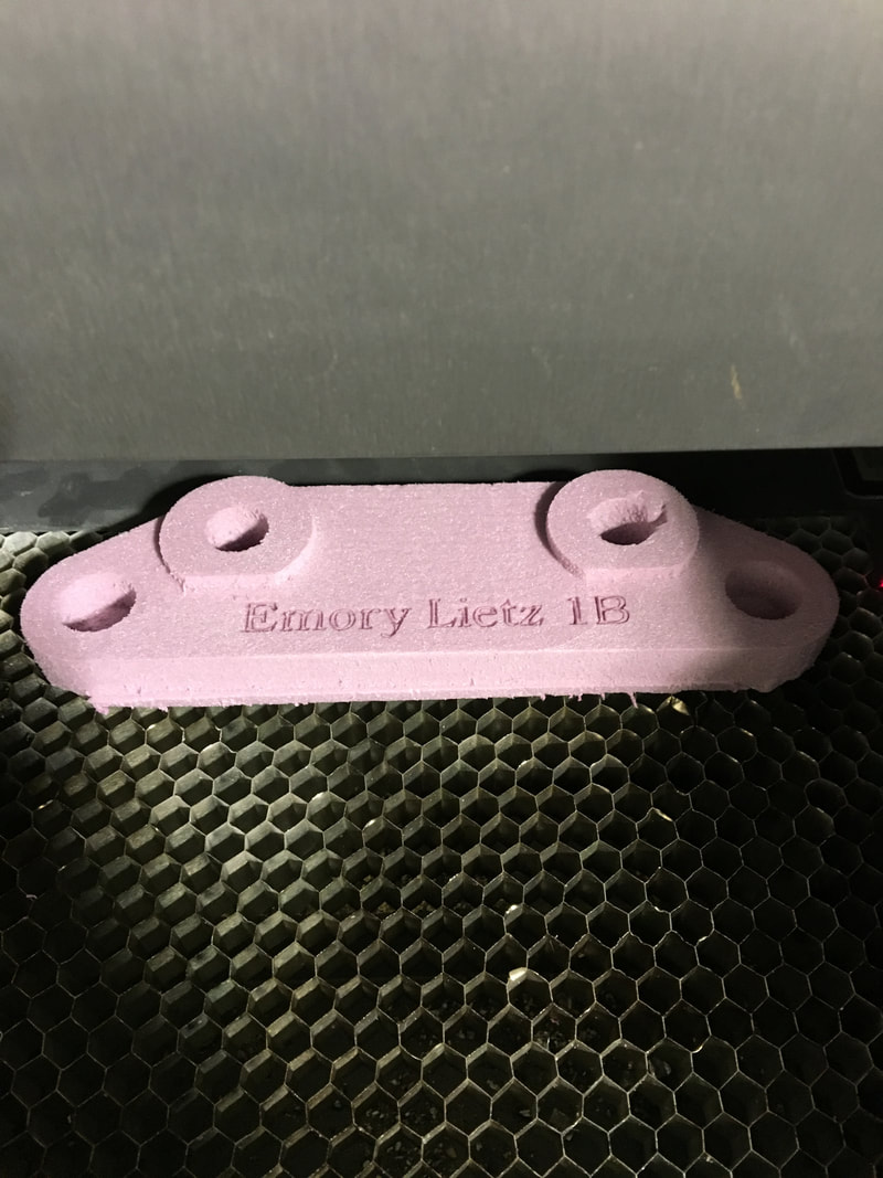
Here's the final product!!
As you can see, the mill did not cut completely through the foam, likely because it was bigger than .75". And you can tell that there's a scuff in the upper left circle. I didn't jog the machine away from my project when I removed it from the base, so it ran into the drill bit. That's a good lesson learned. |
Laser Engraved?!
|
|
|
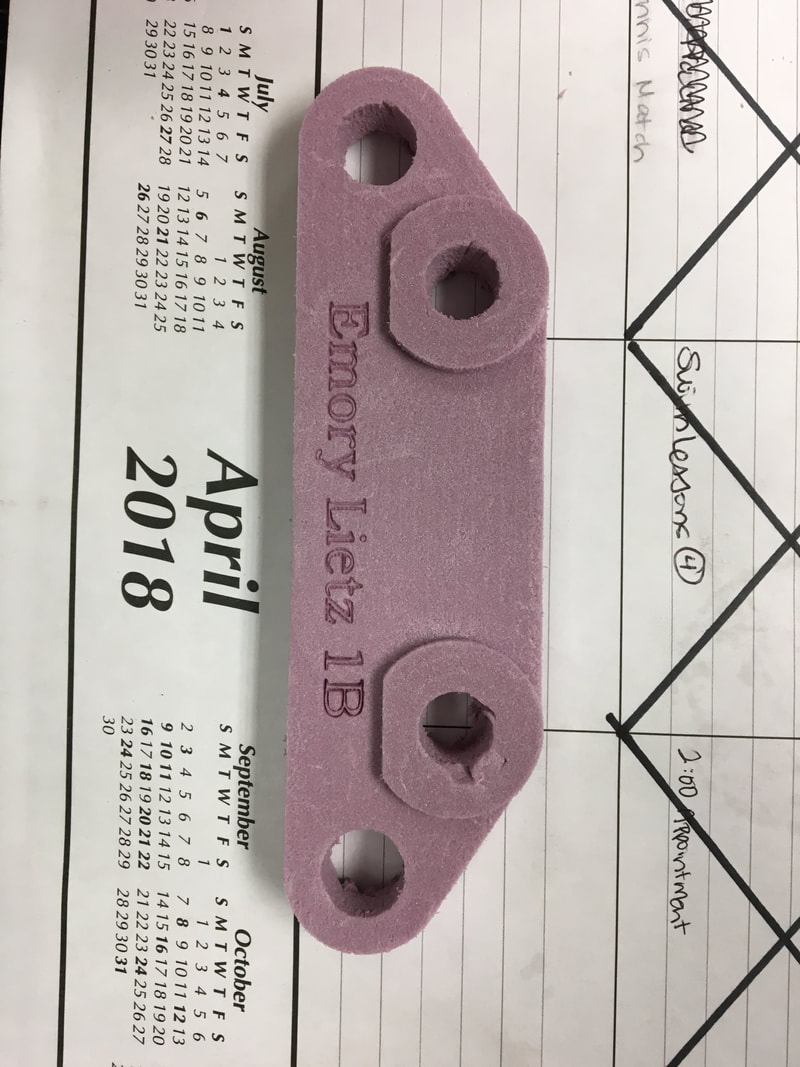
Here's the process I took when laser engraving my brake bracket with my name. I used the same Illustrator file that I used to engrave my maze with, but I made the letters smaller. When I got to the laser, I changed the preferences so that blue speed was 100% and power was 14%.
I lined up the top edge with the top of the bed and chose my laser space. After checking all corners and turning the exhaust on, I hit play and watched the laser work its magic.
I lined up the top edge with the top of the bed and chose my laser space. After checking all corners and turning the exhaust on, I hit play and watched the laser work its magic.
Summary
This project was the first project in IDEA that had a real-life application. In this unit, I learned how to read and interpret blueprints in order to 3D model the figure in Inventor. With this, I also learned a new constraint: tangent. This tangent constraint lined up the line segment and the circle of the brake part.
In addition to this new knowledge of Inventor, I also learned new tools in Fusion 360. For the maze project, we used the 2D Contour from the geometry tab to create our paths. For this project, we familiarized ourselves with the 3D Adaptive Clearing. Finally, when converting our Fusion 360 file to G Code, we selected "Tormach Path Pilot" for the mill, instead of " Forest Scientific", as we did for the router.
In addition to this new knowledge of Inventor, I also learned new tools in Fusion 360. For the maze project, we used the 2D Contour from the geometry tab to create our paths. For this project, we familiarized ourselves with the 3D Adaptive Clearing. Finally, when converting our Fusion 360 file to G Code, we selected "Tormach Path Pilot" for the mill, instead of " Forest Scientific", as we did for the router.
